🚚Free delivery🇫🇷 and 🇧🇪 for the purchase of a complete kit
Installing a bike electrification kit may seem daunting at first, but don’t panic! Here are a few steps to help you install your bike electrification kit safely and efficiently:

To install like a pro, make sure you have the following tools and consumables at your disposal:
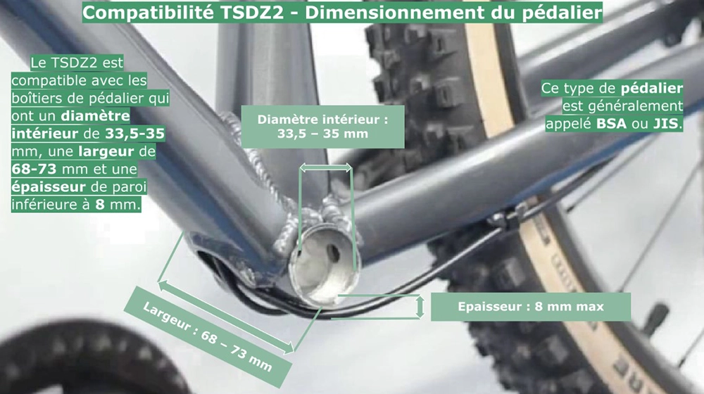
Position the motor in the bottom bracket.
Make sure the motor does not touch the frame (this could interfere with the torque sensor and affect motor durability).
If necessary, add spacers (5 mm washers supplied).
The motor shaft must protrude at least 10 mm to allow the M33.5 mm nut to be screwed on.


1- Insert the screws with spacers into the back of the mounting plate.

2- Fix the mounting plate to the motor without forcing it, adding a few drops of threadlocker is recommended.

Screw on the clamp by hand without forcing.
If your frame doesn’t allow the clamp to be inserted correctly, use threadlocker on the M33.5 grey nut and tighten to the correct torque (see below).

In 4 steps, tighten the screws that lock the motor in position:

1- Tighten the M33.5 grey nut (40N.m), it is strongly recommended to add “removable” threadlocker.

2- Screw in the M5x20 mounting plate screws (10N.m)

3- Screw the clamp firmly to the frame using the counterplate and the M8x50 screw.

4- Screw the clamp firmly to the motor using the M8x40 screw.

Install the display on the handlebar, then tighten the screws without forcing.
For EXPERT display (860C), position the correct rubber adapter according to handlebar diameter and also add the control near the left-hand grip.
For the PRO display (DZ41), position the display as close as possible to the left handle.

Adjust the cable length to maintain handlebar rotation range (tip: turn the handlebars all the way to the side opposite the cable, then adjust easily).
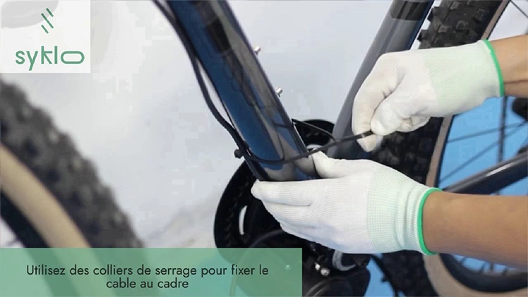
Then use cable ties to secure the cable to the frame (take care not to interfere with brake and gear cables and sheaths).
Secure the speed sensor with two clamps.


Attach the speed sensor magnet to a spoke, using a flathead screwdriver or pliers to tighten firmly.
Check that you have correctly positioned the magnet on the spoke (the screwdriver recess should be opposite the sensor) and that you have precisely adjusted the position of the magnet in relation to the sensor, ensuring alignment with the arrow drawn on the sensor. The ideal spacing is between 10 and 15mm.
Check the ideal position for the battery by aligning the holes in the holder with the inserts in the bottle holder, and make sure you’re able to manoeuvre the battery once it’s installed (you’ll need a minimum of clearance to remove it from the holder).
Firmly screw the battery holder screws to the frame using the inserts provided for the bottle holder.

Connect the battery cable according to the color code (red to red and black to black).
Connect the display (large cable with black ferrule) and the speed sensor (cable with yellow ferrule) with their respective cables on the motor side, following the coding (align the arrows on each cable to be connected).

Important Make sure that the cables are firmly seated and watertight. Also make sure that the cables don’t hang down or get snagged, and take the time to add as many cable ties as necessary to keep the cables held tightly against the frame.

Tighten the M8x14 screws on the cranks (supplied in the kit) very firmly (40 N.m), then fit the pedals (not supplied).
Fit and adjust the chain if necessary; the chainring supplied with the motor is a 42-tooth chainring (fastening adaptable to the dimensions of the standard 110 BCD, if you wish to change chainring).


Visit us and electrify your bike today!